|
| |
| |
| |
Ultrasonic Inline Flow Meters |
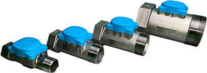 |
Ultrasonic Inline Flow Meters are engineered to elevate water treatment and usage measurement. The ultrasonic inline flow meter module operates as a pulse generating device with corresponding K Factor for accurate flow measurement when connected to commonly used industry controls. Made in USA. |
| |
Features
• Real-time monitoring allows immediate detection of leaks and water usage irregularities,
enabling water conservation
• Innovative use of ultrasonic technology uses no moving parts within the water stream to
increase service life
• Stainless steel construction ensures durability & reliability even in the most demanding environments
• Familiar pulse output mode operation allows meter to be applied to wide variety of control devices
• Meter module can be updated or serviced without removing meter body from plumbing
|
Accuracy over an extended period of time
• Less clogging, and less wear and tear
• Passivated surfaces and materials resist scaling
• Highly visible LED flow indicator
• Male threaded inlet adapter for direct mating to treatment control valve
• Boss provided on outlet for drilling/tapping 1/4 inch sample port |
 |
| Specifications |
• Max Pressure ................................................. 250psi (8.6 bar)
• Water Temperature Range ............................... 34°F (1°C) to 100°F (38°C)
• Operating Power ............................................. 5 to 24VDC*
|
| *Confirmed to work with Clack, Fleck, Autotrol, Culligan, and AQ Matic controllers |
| |
| Wetted Parts
|
• Meter Body ................................................... CF8M† Stainless Steel
• Signal Reflection Plate .................................... SS316
• Transducer Housing ....................................... Glass-filled Polyphenylene Sulfide (PPS)
• O-ring .......................................................... EPDM
|
† CF8M is a cast, molybdenum-bearing austenitic stainless steel alloy, equivalent to the wrought AISI 316
stainless steel, known for its enhanced corrosion resistance, especially in chloride-rich environments. |
| |
| |
| Operating Range |
| Part Number |
Pipe Size |
Thread Type** |
Low Flow Threshold |
Typical Flow 0.1 ft/sec to 10ft/sec |
Max Flow 16ft/sec |
K Factor Pulses/ Gal |
QA-FM100 |
1.0 |
NPT |
|
0.3 to 24.5 gpm
(1.1 to 9.3 lpm) |
39 gpm
(147 lpm) |
40 (10.57/ Liter) |
| QA-FM150 |
1.5 |
NPT |
0.25 gpm (0.95 lpm) |
0.6 to 55.1 gpm
(2.3 to 209 lpm) |
88 gpm
(333 lpm) |
30 (7.93/ Liter) |
| QA-FM200 |
2.0 |
NPT |
0.45 gpm (1.7 lpm) |
1.0 to 98.0 gpm
(3.8 to 371 lpm) |
156 gpm
(590 lpm) |
20 (5.28/ Liter) |
| QA-FM300 |
3.0 |
NPT |
1.4 gpm (5.3 lpm) |
2.2 to 220.5 gpm
(10.6 to 835 lpm) |
353 gpm
(1336 lpm) |
10 (2.64/ Liter |
|
| ** Available with BSP thread. Add 'BSP' to end of part number. Example: QA-FM100BSP. |
| |
|
| |
| |
| Identification |
NPT
Female Outlet
Male Inlet
BSPT
Female Outlet
Male Inlet |
 |
On Power Up
LED flashes indicator of power applied and sequence
to show how dip switches are set for meter size.
|
| |
|
|
# of Flashes |
|
|
Model |
|
inches |
|
| |
|
1 Flash |
|
|
QA-FM100 |
1 inch |
| |
|
2 Flashes |
|
|
QA-FM150 |
1.5 inches |
| |
|
3 Flashes |
|
|
QA-FM200 |
2 inches |
| |
|
4 Flashes |
|
|
QA-FM300 |
3 inches |
During Operation
LED flashes as forward flow is sensed within meter. Flashing is proportional to the rate of flow sensed.
Higher flow rate generates higher frequency of flashing. |
| |
XX = K Factor
DOM= Date of Manufacture
(DDMMYYYY) |
|
| |
| |
| |
 |
|
| Part Number |
Overall Length
(Dim A) |
Overall Height
(Dim B) |
Hex Width
Flat to Flat
(Dim C) |
Weight |
| QA-FM100 |
5.6 inches |
2.5 inches |
1.6 inches |
1.7 lbs |
| QA-FM150 |
5.6 inches |
3.0 inches |
2.1 inches |
2.0 lbs |
| QA-FM200 |
5.6 inches |
3.5 inches |
2.6 inches |
2.4 lbs |
| QA-FM300 |
6.9 inches |
4.5 inches |
3.8 inches |
4.2 lbs |
|
Available with BSP thread.
Add 'BSP' to end of part number. Example: QA-FM100BSP
|
| |
|
| |
| |
| |
|
|
| |