Retention Tanks
swtwater.com Fiberglass Wrapped & PE Liner
SWT's Fiberglass Wound Retention Vessels with PE Liner    
Retention Tanks are designed to provide extended contact time when adding chemicals into the water stream. They are perfect for chlorine, KmNO4, phosphate, or acid feeds, and more. When used in conjunction with a static mixer, these vessels will make sure that the chemicals are properly blended into the water supply. Retention Tanks are designed for long life in corrosive environments and when working with strong chemical additives or oxidizing agents.
 
FEATURES:
Seamless inner shell of molded polyethylene for impact and corrosion resistance
Wound with miles of epoxy covered fiberglass filament for superior strength and light weight
FDA and/or NSF-approved materials
Equipped with bottom drain port
Available in blue
5 year warranty
 
OPERATING PARAMETERS:
75 psi maximum operating pressure
120°F maximum operating temperature
 
 
FIBERGLASS WRAPPED RETENTION TANKS WITH POLYETHYLENE LINER
Part
Number
Tank Size
Inches
System Connections (PVC) Height Capacity
Top Bottom Inches mm Gallons Liters Cubic
Feet
TS-CT30-QC 16 x 40 1.25" FNPT 1.25" MNPT 44.0 1,117.6 30.0 113.6 4.0
TS-CT40-QC 16 x 53 1.25" FNPT 1.25" MNPT 56.0 1,422.4 40.0 151.4 5.3
TS-CT40SQ-QC 21 x 32 1.25" FNPT 1.25" MNPT 35.0 889.0 40.0 151.4 5.3
TS-CT80-QC 24 x 50 1.25" FNPT 1.25" MNPT 67.0 1,701.8 80.0 302.8 10.7
TS-CT120-QC 24 x 70 1.25" FNPT 1.25" MNPT 73.0 1,854.2 120.0 454.2 16.0
Related Equipment Available:
Inline Static Mixer (Recommended—See illustration below.)
Chemical Feed Pumps
 
 
SWT's Retention Tank Schematic
 
 
VACUUM PROTECTION & FLEX CONNECTORS
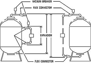
Fiberglass/composite pressure vessels are rated for an internal negative pressure of 5-inches Hg (17 Pa) vacuum below atmospheric. If negative pressure could ever exceed 5-inches Hg (17 Pa), an adequate vacuum breaker must be installed between the pressure vessel inlet and any valves (see illustration right). For enclosed tank applications, the vacuum breaker should be installed at the highest location in the system plumbing.

System connections to the pressure vessel must accomodate vertical expansion between side, top, and bottom openings. Either flexibility in piping or flex connectors, as shown here, are recommended.
SWT Vacuum Breaker and Flex Connector installation diagram

See SWT Vacuum Protection
and Flex Connector Products


Safe Water Technologies, Inc.
996 Bluff City Boulevard
Elgin, IL 60120 USA
 
 
Telephone: +1.847.888.6900
Facsimile: +1.847.888.6924
E-mail: info@swtwater.com
https://www.swtwater.com

Last Updated: April 1, 2024