| Air Injectors |
| Micronizer Venturi Air Injector | |
| Request For Quote | |
|
|||||||||||||||||||||||
|
|||||||||||||||||||||||
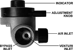
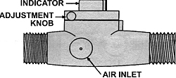
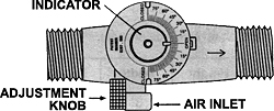
| NOTES: Micronizer air draw is adjusted with the adjustment knob. DO NOT ATTEMPT TO ADJUST THE UNIT WITH THE INDICATOR DIAL—GEAR DAMAGE WILL RESULT! The indicator dial shows the position of the built-in bypass valve (i.e. percent open or closed). It does not indicate the amount of air draw. Note: Increasing the adjustment to the closed position forces more water through the venturi and increases the pressure drop through the micronizer. Micronizer air draw is determined by the overall (total) pump run time. Each time the micronizer is adjusted, the pump time MUST be rechecked and the air draw at the micronizer MUST be monitored and timed until the air draw time is 30 to 50 percent of the overall pump time. The pointer on the dial indicates that the micronizer is fully open when it is in line with the plumbing (12 oclock position). This position will give the least amount of air draw. When the pointer on the dial is in the 90 degree position (3 oclock or 9 o'clock), the micronizer will draw the maximum amount of air. The dial will go left or right and give the same results. The markings on the dial are for a reference only and DO NOT INDICATE THE PERCENTAGE OF AIR DRAW. The air does not vent at every pump cycle as some may expect to hasppen. If the system is working correctly, the excess air will only vent when the float on the air volume control opens to allow this to happen. The float on the air volume control will open only when the air in the upper portion of the pressure tank increases to the point that the water level is forced lower than the float allowing the vent on the float to open. Once this excess air is allowed to vent to a safe location, the process starts all over. |
|||||||||||||||||||||||
| TROUBLESHOOTING: If the micronizer will not draw air... 1. Check to make sure that the unit is installed with the arrow facing the direction of the flow. 2. Check the system flow rate as described above. 3. Check to see that the system pressure does not exceed 60 psig. 4. Remove the micronizer and check for obstructions. 5. If the micronizer leaks at the draw hole, depressurize the system and remove the cap. Remove the rubber check ball and rinse it in water. Make sure that no grit is stuck in the ball check. Reinstall the cap and DO NOT OVERTIGHTEN. |
|||||||||||||||||||||||